
This blog post is a bit off the topic from the Audi ones I have been posting lately. But I thought it was interesting enough to warrant an article. My second vehicle is a 1985 Honda NH80 scooter. I bought this vehicle last summer. I took the Audi off the road so I could replace the turbo, and I knew it would be on blocks for most of the summertime. So I bought the scooter to have some simple and cheap transportation while working on the car. And cheap it was. Driving the scooter all summer long cost only $50 in gas, and another $150 to insure.
My latest idea for the scooter is to install LED turn signals to replace the original incandescent bulbs. All the lights on this scooter are pretty weak and I wanted to make sure I am more visible on the road. As I found out LED’s are not a simple swap out. Scooter, and motorcycle electrical systems are wired in such a way that a bit more work needs to be done to make this upgrade work.
Specifically, my scooter has a turn signal indicator, and clicky noise maker that are wired across both the left and right turn signal circuits. This does not seem intuitive, but its true. To simplify wiring, and keep costs down the bulbs of the opposite side to the signal being indicated are used to pass current that both lights the signal indicator, and makes the click noise. It does this without drawing enough current to illuminate the bulbs.
But LED’s work very differently than a regular bulb. Incandescent bulbs light up purely through the resistance of the filament to the current passing through it. A LED is not a resister, its a diode. (Light Emitting Diode). A diode only allows power to flow in one direction and it needs a certain voltage level before it will pass current in the forward direction. Also LED’s will light up using much less current than than a regular bulb. So now the bulbs on the opposite side are now lighting up, AND none of the bulbs are blinking!
There are two things that need to be addressed to fix this problem. The first is to separate the two sides of the turn signals by adding some diodes, and the second is to replace the turn signal relay with one that is designed to work with LED bulbs.
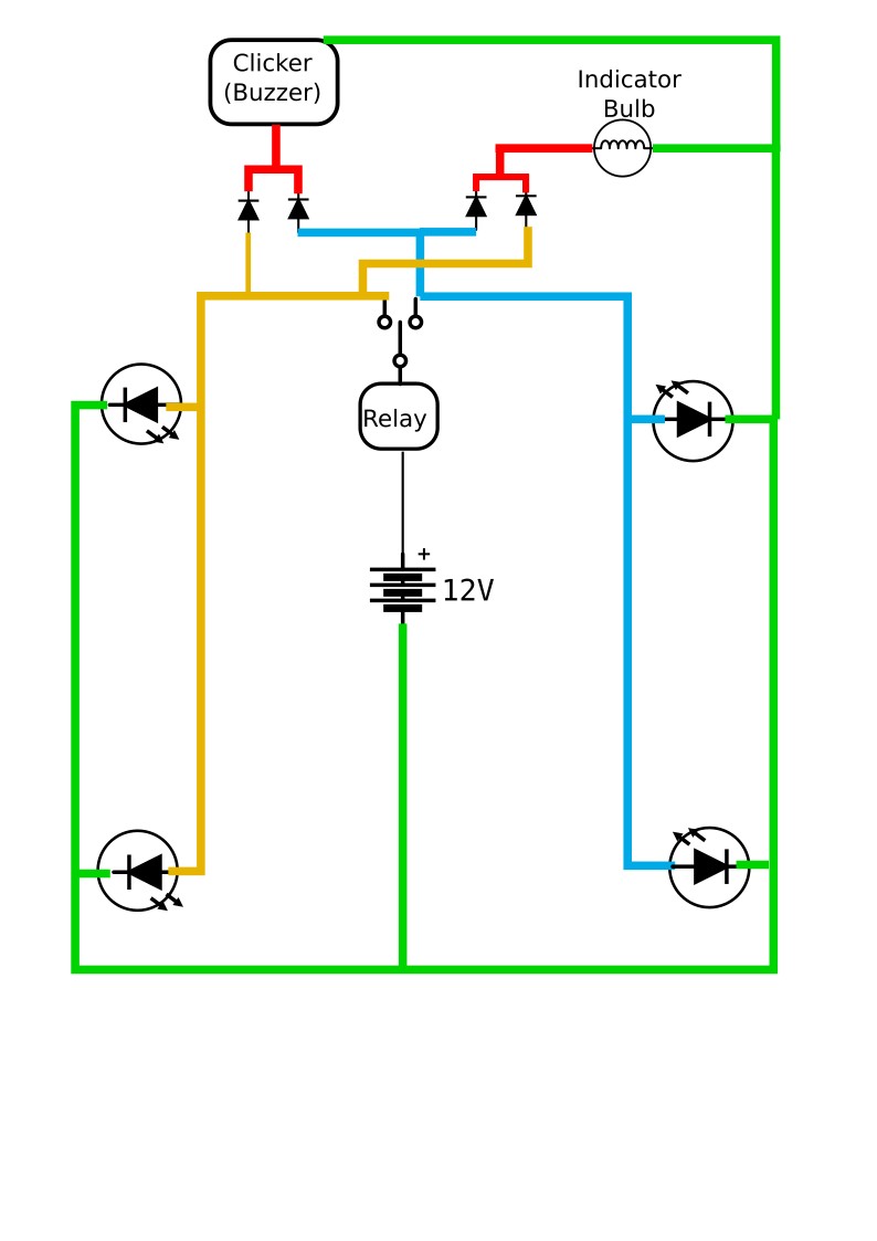
To start a couple of diode pairs need to be added to one side of the circuit going to the noise clicker, and to the indicator bulb. The second wire from those components then get wired directly to ground. This causes the current to bypass the bulbs on the opposite side of the bike. The ones you don’t want blinking.
The second thing is to replace the blinker relay with the one made for LED
Here are the parts needed to complete this job as well as some tools that come in handy. The following links are Amazon affiliate links.

Light bulbs. These will fit a standard single filament bulb type used on most motorcycles.
Diode pairs. These are what separate the left and right side circuits.


Turn Signal Relays made for use the LED bulbs. Normal signal relays expect a higher current than what LED’s draw and so don’t function correctly with LED bulbs.
Terminal Connectors with Wire Strippers. Most motorcycles and scooters use a round terminal connector. I found these ones connect directly to the factory Honda connectors on my scooter


Add comment